Test Systems
GtestWorks Automated Testing Platform
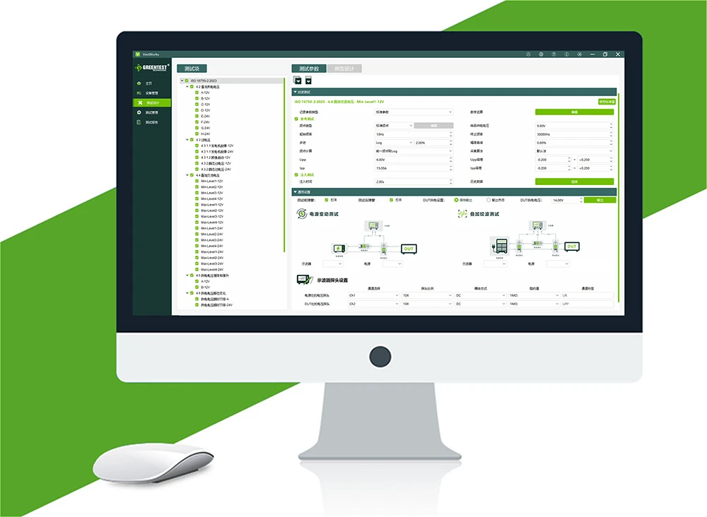
VectWorks 3.0 Electrical Performance Test Software


Medical Electrical Equipment - Part 1: General Requirements for Basic Safety and Essential Performance
This standard specifies the general requirements for basic safety and essential performance of Medical Electrical Equipment (ME Equipment) and Medical Electrical Systems (ME Systems), applicable to the design, production, inspection, and use of various medical electrical equipment. Compared with the previous version, the new edition introduces risk management concepts, making safety testing requirements more systematic and rigorous.
| No. | Test Item | Description | Remarks |
|---|---|---|---|
| 4.11 | Input Power | Measure steady-state input, not exceeding 110% of the marked rated value | + Power Measurement Module |
| 8.4.2 | Accessible Parts and Applied Parts | Earth leakage current, touch current, patient leakage current, patient auxiliary current | + LCR Module + Power Measurement Module |
| 8.4.3 | ME Equipment Intended to be Connected to Supply via a Plug | Voltage between each pin and between power pins and enclosure ≤60V at 1s after disconnection; if voltage exceeds 60V, stored charge ≤45μC | + LCR Module |
| 8.4.4 | Internal Capacitance Circuits | Residual voltage ≤60V; if voltage exceeds 60V, stored charge ≤45μC | + LCR Module |
| 8.5.5.1 | Defibrillation Protection | Common-mode test + Differential-mode test | + 5kV Test Circuit |
| 8.5.5.2 | Energy Reduction Test | 100Ω load absorbs defibrillator energy | + 5kV Test Circuit |
| 8.6.4 | Impedance and Current-Carrying Capacity | Impedance between protective earth and any earthed part ≤100mΩ or 200mΩ | + Ground Resistance Measurement Module |
| 8.7 | Leakage Current and Patient Auxiliary Current | Earth leakage current, touch current, patient leakage current, patient auxiliary current | + Test Circuit + Isolation Transformer Module + Leakage Current Measurement Module |
| 8.8.3 | Dielectric Strength | Initial test voltage ≤0.5*specified test voltage, increase gradually to specified value within 10s, maintain for 1min, decrease to less than half the specified value within 10s | + Withstand Voltage Module + Isolation Transformer Module |
| 11.6.6 | Cleaning and Disinfection | Dielectric strength and leakage current test | + Withstand Voltage Module + Leakage Current Measurement Module |
| 15.5.1.1 | Transformers | Short-circuit test + Overload test | + Winding Measurement Module + Temperature Acquisition Module |
| 15.5.2 | Dielectric Strength | Apply 5 times rated voltage or 5 times the upper limit of rated voltage range, frequency ≥5 times rated frequency between winding terminals | + Withstand Voltage Measurement Module |
| 16.6 | Leakage Current | Touch current, earth leakage current of multi-socket outlets, patient leakage current | + Test Circuit + Isolation Transformer Module + Leakage Current Measurement Module |
| No. | Model | Name | Remarks |
|---|---|---|---|
| 1 | PTS Series | PTS Series Power Supply | |
| 2 | VectWorks | Electrical Performance Testing Software | Host Computer Software |
| 3 | PTS Series | Power Measurement Module | Optional |
| 4 | PTS Series | LCR Module | Optional |
| 5 | PTS Series | Ground Resistance Measurement Module | Optional |
| 6 | PTS Series | Isolation Transformer Module | Optional |
| 7 | PTS Series | Leakage Current Measurement Module | Optional |
| 8 | PTS Series | Winding Measurement Module | Optional |
| 9 | PTS Series | Withstand Voltage Measurement Module | Optional |
For details, please contact our company
VectWorks Electrical Performance Testing Software is a software developed by GreenTest Technology based on the GtestWorks automated testing platform. Its engine is based on dynamic test script execution, facilitating easy and direct configuration of test sequences without requiring specific knowledge of remote instrument control. Users only need to configure the test items and test levels, providing high flexibility.
The software provides users with standard-compliant test templates, enabling remote parameter setting, data acquisition, waveform editing, configuration import/export, report viewing, etc., achieving automation of complex tests.

Closed-Loop Dynamic Testing
Integrates real-time monitoring and dynamic feedback mechanisms

High/Low Voltage Superimposed Ripple Testing
Complies with standard calibration requirements (including Upp, Ipp ripple monitoring)

Power Supply & Amplifier Architecture
Compatible with bipolar power supply and amplifier architecture solutions